Magnetic toolchanger V1
End effectorExperimental printer tool changer that rotates permanent-magnet rings to attach lightweight tools; requires custom docks and Klipper configuration. [1]
Build & first use →Official websiteUpstream build guideBill of materials
- For
- Builders developing custom printer tool-changing mechanisms. [1]
- Cost
- No current cost yet. Upstream bill of materials [2]
- Source rights
- Named licenses are documented by part. Review licenses
- Unknowns
- host computer, tools, operating system not fully established. Review gaps
Source researched · Not tested by us
Sources checked · Research details
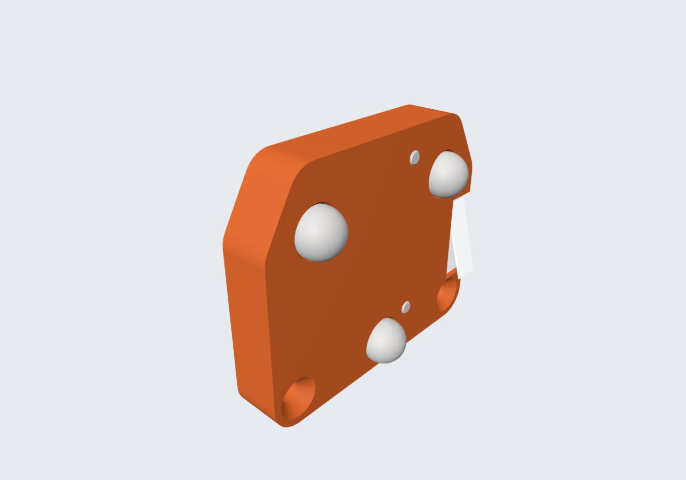
CAD render fallback — view still image
Overview
This experimental tool changer is intended for lightweight printer tools such as Bowden hotends. A geared stepper rotates a ring of permanent magnets so that the matching tool is attracted or repelled. Steel balls and L-shaped profiles locate the tool at six contact points. The author cautions that the magnets do not reliably hold heavier tools; the repository does not establish a rated payload. [1]
Is this for you?
- Known limitations
- Lightweight tools only; no rated payload or docking repeatability established.
- Custom carriage, docks and complete host configuration required.
- Dropped-tool switch handling is not implemented; some tool files assume an inverted head.
Editorial classification; no physical qualification.
3D preview
Magnetic toolchanger V1 toolhead. Toolhead assembly geometry only; dock, payload tool and host printer are separate.
The 3D preview loads after the page.
Drag to orbit · Scroll or pinch to zoom · Right-drag to pan. Use the view buttons for front, side and top views. The tree shows names supplied by the source; unnamed bodies remain labeled as such.
Download original STEP · File checksums and provenance
Separate bodies can be inspected in the model tree. Explode is a viewing aid, not an assembly sequence.
Model sources
The preview uses the linked original design. Source grouping is retained where present; the caption identifies whether this is an assembly or one component.
Source, license and scale
Source: totaldesaster, revision 6910d2d387b1470493b4ac928b332b196d3363fc. Original and preview: GPL-3.0. Preview conversion by Open Source Robotics; original file unchanged. Preview coordinates are centered and rounded to six decimal places. STEP preview triangulated in millimetres. No physical part tested.
Viewer: three-cad-viewer 5.0.7 (MIT license). Confirm scale and manufacturing settings before printing.
Hardware & parts
Assembly & first use
Open the upstream getting-started guide [1]
Cost
No current, complete configuration-specific build cost has been established for this profile.
Project notes
Use the V1 files as one configuration
The repository contains an earlier pogo-pin prototype and a V1 arrangement with each tool wired separately. This profile and its toolhead preview use V1. Start with that version's toolhead, dock and selected tool files instead of mixing in the abandoned electrical connector arrangement. The toolhead preview excludes the dock, payload tool and printer. [1] [2]
The V1 parts list names a 28BYJ-48 stepper, KW11-3Z microswitch, coupler balls and a linked disc-magnet part. The illustrated tool example uses a Trianglelab Arethusa hotend; its L-profile stock is not fully specified. Upstream recommends at least four walls and 25% infill for the printed mechanical parts. These recommendations and supplier links are not a complete current shopping quote. [2]
The carriage and configuration are still your work
The documented host moves the head in both X and Y, with CoreXY given as an example, and needs a spare stepper driver. A printer-specific carriage and dock base must be designed. Upstream also calls for modifying the motor for a normal stepper driver; that modification was not independently performed here. Some supplied tool designs assume an upside-down head, so check the selected tool's orientation rather than treating all files as interchangeable. No cobot or delta-robot interface is demonstrated. [1] [5]
The Klipper file is explicitly an incomplete example. Its pins, dock coordinates, offsets and extruder definitions must be reconciled with the host machine. The example assumes tool 0 at startup. A microswitch is present to detect a dropped tool, but the README says that detection is not yet implemented in software; the switch alone should not be treated as an operating interlock. These gaps make this a mechanism-development project rather than a ready-to-run tool-changing upgrade. [1] [2] [3]
The source files carry GPL-3.0. The original V1 toolhead STEP is supplied unchanged, with a derived triangulated preview and shaded CAD image under the same license. No physical assembly, retention-force measurement, docking-cycle test or controller bringup was performed for this profile. [4]
What we checked
Source research only; no hardware build, procurement, calibration or performance testing.
Not yet established
- Requirements: operating system, host computer, tools
- A step-by-step setup summary
Updates
- Upstream last updated
- Not established
- Latest release
- Not established
- Profile updated
- Sep 30, 2026
- Sources last checked
- Sep 30, 2026
- Next review
- Oct 30, 2026
- Reviewed revision
6910d2d
Source files and licenses
Licensed mechanical design with purchased components and unresolved integration requirements. Experimental printer tooling; not a verified robot-arm interface.
| Layer | Availability / license |
|---|---|
| mechanical design | available · GPL-3.0 Repository GPL applies to supplied design files; purchased components assessed separately. [1] [4] |
| electronics | not found · License not fully assessed A complete revision-matched source set for this layer was not established in the inspected repository; this is not a claim that external components are closed. [1] [3] |
| firmware | not found · License not fully assessed A complete revision-matched source set for this layer was not established in the inspected repository; this is not a claim that external components are closed. [1] [3] |
| software | available · GPL-3.0 Incomplete example Klipper macros/configuration, not the complete external firmware or a ready-to-run host configuration. [1] [3] [4] |
| documentation | available · GPL-3.0 Repository GPL applies to supplied design files; purchased components assessed separately. [1] [4] |
No learned policy or dataset selected for this mechanical configuration.
References
Each source links to the exact revision we read. “Used for” shows where this page relies on it.
- S001 Mechanism overview
Revision, date & where cited
github.com · revision
6910d2d· README.md at · Accessed Sep 30, 2026
Used for: Overview, Is this for you?, Hardware & parts, Assembly & first use and 3 more - S002 V1 parts and print settings
Revision, date & where cited
github.com · revision
6910d2d· Version 1/README.txt at · Accessed Sep 30, 2026
Used for: Is this for you?, Hardware & parts, Assembly & first use, Use the V1 files as one configuration and 1 more - S003 V1 Klipper example
Revision, date & where cited
github.com · revision
6910d2d· Version 1/Klipper Config.txt at · Accessed Sep 30, 2026
Used for: Is this for you?, Hardware & parts, The carriage and configuration are still your work, Source files and licenses - S004 totaldesaster/toolchanger: LICENSE
Revision, date & where cited
github.com · revision
6910d2d· LICENSE at · Accessed Sep 30, 2026
Used for: The carriage and configuration are still your work, Source files and licenses - S005 Tool orientation note
Revision, date & where cited
github.com · revision
6910d2d· Version 1/Tools/readme.txt at · Accessed Sep 30, 2026
Used for: The carriage and configuration are still your work
Correction guidance · Discussion is not enabled · Profile format 0.6.0-draft.1