TriFinger
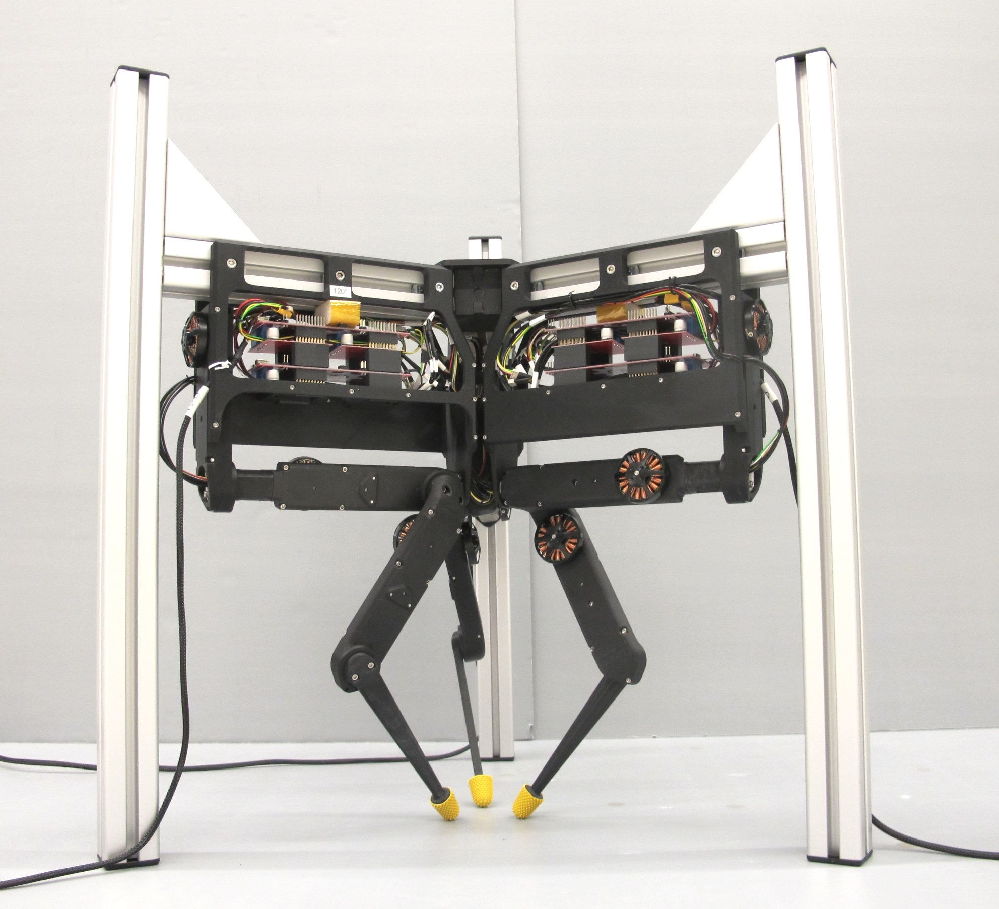
Robot / hardware buildTriFingerEdu v1 is a nine-axis torque-controlled manipulation platform built from three FingerEdu modules, with a documented TI evaluation-board control route. [5] [6] [7]
Build & first use →Official website
- For
- Researchers able to fabricate actuator hardware and integrate real-time motor control [1]
- Cost
- No current cost or bill of materials established yet.
- Source rights
- Named licenses are documented by part. Review licenses
- Unknowns
- tools, operating system not fully established. Review gaps
Source researched · Not tested by us
Sources checked · Research details

Licenses & related hardware
- License
- BSD-3-Clause · Details by part
Overview
Is this for you?
- Known limitations
- Firmware flashing guide leaves toolchain/source acquisition instructions unfinished
- Linked actuator testing page has no substantive test procedure
- Variant-specific hardware coverage does not establish other TriFinger configurations
Editorial assessment of preserved documentation.
3D preview
TriFingerEdu finger assembly. The first-party TriFingerEdu description: three FingerEdu modules at source zero joint positions. The table, enclosure, electronics and task objects are not included in this model. This is a simulation visual reference, not a verified manufacturing assembly.
The 3D preview loads after the page.
Drag to orbit · Scroll or pinch to zoom · Right-drag to pan. Use the view buttons for front, side and top views. The tree shows names supplied by the source; unnamed bodies remain labeled as such.
Download original URDF source bundle (ZIP) · File checksums and provenance
Separate bodies can be inspected in the model tree. Explode is a viewing aid, not an assembly sequence.
Model sources
The preview uses the linked original design. Source grouping is retained where present; the caption identifies whether this is an assembly or one component.
Source, license and scale
Source: Max Planck Gesellschaft / Open Dynamic Robot Initiative contributors, revision a1dfd635750ab9466e6dd5a421848819b1c62d7a. Original and preview: BSD-3-Clause. Preview conversion by Open Source Robotics; source files unchanged inside the downloadable bundle. Preview coordinates are centered and rounded to six decimal places. URDF visual origins, mesh scales and joint transforms applied at zero joint positions, then metres converted to millimetres. No physical part tested.
Viewer: three-cad-viewer 5.0.7 (MIT license). Confirm scale and manufacturing settings before printing.
What you need
- Host computer
TI electronics guide describes a real-time PC and CAN card for a 1kHz control loop; no host sizing or latency test performed.
Hardware & parts
Assembly & first use
Cost
No current, complete configuration-specific build cost has been established for this profile.
Project notes
Build the fingers and frame as a matched configuration
Each FingerEdu module uses three actuator modules derived from the repository's three-axis leg design. The surrounding shells, printed finger structure and rubber fingertips turn those shared actuator components into a manipulation finger. The frame guide separately lists aluminum profiles, brackets, end caps, printed connectors and 3 mm polycarbonate barriers. It also names a Basler camera and lens; these references do not establish a complete calibrated perception system. [5] [6]
The actuator v1.1 documentation describes a prepared encoder kit as an alternative to fabricating the motor-shaft assembly and related machined pieces. Upstream calls the shaft assemblies functionally interchangeable, but present-day kit availability and a complete delivered budget were not verified. The shared actuator core and an assembled finger are different cost and weight scopes. [6] [9]
The printing guide distinguishes structural FDM/SLS parts from precision SLA or multijet pulleys. Bearing-seat tolerances and print orientation matter: a file being present does not establish that arbitrary print settings produce usable mechanics. The TriFingerEdu directory also distinguishes simplified visualization meshes from other design files. [5] [10] [12]
The documented electronics use TI evaluation boards
The FingerEdu instructions select the Texas Instruments evaluation-board route and specify 24 V power and two CAN communication channels per finger module. The electronics overview describes the F28069M LaunchPad with DRV8305 booster boards and a real-time PC/CAN-card control loop at 1 kHz. These are documented architecture requirements, not measured end-to-end performance on a catalog-built system. [6] [7]
The guide calls out jumper removal to isolate USB-connected host equipment from externally supplied power. It distinguishes programming through USB from running stored firmware, with different boot-switch settings. The separate flashing guide further distinguishes a RAM/debug build from a flash build and notes that detaching the debugger does not stop the running program. No wiring, flashing or motor motion was performed here. [7] [8]
Available designs do not constitute a complete bring-up procedure
The flashing document leaves the Code Composer installation and source-checkout steps unfinished. The linked actuator testing page contains headings and navigation but no substantive test procedure. Those gaps remain relevant even though assembly and component documentation are extensive. Exact firmware, host software, calibration and complete-system qualification still need configuration-specific work. [8] [11]
The preserved hardware repository has a BSD-3-Clause license. Purchased TI boards, encoder components, firmware dependencies and external software do not automatically inherit that license. This profile establishes researched TriFingerEdu design coverage; it does not claim a tested build, complete sourcing quote, reproduced torque performance or demonstrated manipulation policy. [3] [5] [7] [9]
What we checked
Source research only; no installation, physical build or performance test performed. No affiliate links added.
Not yet established
- Requirements: operating system, tools
- A step-by-step setup summary
Updates
- Upstream last updated
- Sep 6, 2022 [2]
- Latest release
- Not established
- Profile updated
- Oct 25, 2026
- Sources last checked
- Oct 1, 2026
- Next review
- Oct 31, 2026
- Reviewed revision
- 66af1522b4fba0ec4a1d7790e66f5e4652208d30 (commit snapshot; no published stable release found) · combined hardware and software repository
Source files and licenses
Available project sources support research coverage; complete build and commercial qualification remain separate.
| Layer | Availability / license |
|---|---|
| mechanical design | available · BSD-3-Clause TriFingerEdu/FingerEdu frame and actuator design files; visualization meshes are separate from fabrication parts. No geometry or physical build verification claimed. [3] [5] [6] [9] [12] |
| electronics | not found · License not fully assessed Selected route documents purchased TI evaluation boards and control/toolchain requirements. Complete matched electronics fabrication, firmware and host-software payloads were not established in this hardware-repository review; not a claim of closed source. [6] [7] [8] |
| firmware | not found · License not fully assessed Selected route documents purchased TI evaluation boards and control/toolchain requirements. Complete matched electronics fabrication, firmware and host-software payloads were not established in this hardware-repository review; not a claim of closed source. [6] [7] [8] |
| software | not found · License not fully assessed Selected route documents purchased TI evaluation boards and control/toolchain requirements. Complete matched electronics fabrication, firmware and host-software payloads were not established in this hardware-repository review; not a claim of closed source. [6] [7] [8] |
| documentation | available · BSD-3-Clause Selected repository documentation; external component documentation retains separate terms. [3] [5] [7] |
Selected torque-controlled hardware configuration does not require a particular learned policy or dataset.
References
Each source links to the exact revision we read. “Used for” shows where this page relies on it.
Project sources
- S001 open-dynamic-robot-initiative/open_robot_actuator_hardware: README.md
Revision, date & where cited
github.com · revision
66af152· Accessed Oct 1, 2026
Used for: Assembly & first use - S002 open-dynamic-robot-initiative/open_robot_actuator_hardware: commit 66af152
- S003 open-dynamic-robot-initiative/open_robot_actuator_hardware: LICENSE
Revision, date & where cited
github.com · revision
66af152· Accessed Oct 1, 2026
Used for: Available designs do not constitute a complete bring-up procedure, Source files and licenses - S004 open-dynamic-robot-initiative/open_robot_actuator_hardware: files
Revision, date & where cited
github.com · revision
66af152· archive file inventory · Accessed Oct 1, 2026 - S005 mechanics/tri_finger_edu_v1/README.md
Revision, date & where cited
github.com · revision
66af152· Accessed Oct 1, 2026
Used for: Overview, Is this for you?, What you need, Hardware & parts and 3 more - S006 mechanics/finger_edu_v1/README.md
Revision, date & where cited
github.com · revision
66af152· Accessed Oct 1, 2026
Used for: Overview, What you need, Hardware & parts, Build the fingers and frame as a matched configuration and 2 more - S007 electronics/ti_electronics/README.md
Revision, date & where cited
github.com · revision
66af152· Accessed Oct 1, 2026
Used for: What you need, The documented electronics use TI evaluation boards, Available designs do not constitute a complete bring-up procedure, Source files and licenses - S008 electronics/details/details_flashing.md
Revision, date & where cited
github.com · revision
66af152· Accessed Oct 1, 2026
Used for: Is this for you?, What you need, The documented electronics use TI evaluation boards, Available designs do not constitute a complete bring-up procedure and 1 more - S009 mechanics/actuator_module_v1/actuator_module_v1.1.md
Revision, date & where cited
github.com · revision
66af152· Accessed Oct 1, 2026
Used for: Build the fingers and frame as a matched configuration, Available designs do not constitute a complete bring-up procedure, Source files and licenses - S010 mechanics/actuator_module_v1/details/details_3d_printed_parts.md
Revision, date & where cited
github.com · revision
66af152· Accessed Oct 1, 2026
Used for: Build the fingers and frame as a matched configuration - S011 mechanics/actuator_module_v1/details/details_actuator_module_testing.md
Revision, date & where cited
github.com · revision
66af152· Accessed Oct 1, 2026
Used for: Is this for you?, Available designs do not constitute a complete bring-up procedure - S012 Complete archive filenames
Revision, date & where cited
github.com · revision
66af152· Preserved archive inventory · Accessed Oct 1, 2026
Used for: Build the fingers and frame as a matched configuration, Source files and licenses - S016 Upstream image and reuse attribution
Media-only review: Upstream photograph of a TriFinger educational manipulation platform configuration. Reuse basis: BSD-3-Clause; inspected LICENSE and the pinned file inventory for nearer notices. Original image unchanged; displayed responsively. This does not refresh technical or cost evidence.Revision, date & where cited
Open Dynamic Robot Initiative, New York University and Max Planck Gesellschaft · github.com · revision
66af152· Image SHA-256 cd43b80c70c5145ceb1098f8932869807b78532aeff6d66b56c7bcfa6837184f; repository · Accessed Oct 25, 2026
Videos
- S013 Open Dynamic Robot Initiative (YouTube channel)
The project’s own YouTube channel, linked from the project’s own documentation. Not reviewed by us for accuracy.Revision, date & where cited
YouTube channel Open Dynamic Robot Initiative · youtube.com · Accessed Oct 4, 2026
- S014 20180914 Optical Foot Contact Switch Demonstration (YouTube video)
Video from the project’s own channel (Open Dynamic Robot Initiative), linked from the project’s own documentation. Not reviewed by us for accuracy.Revision, date & where cited
YouTube video Open Dynamic Robot Initiative · youtube.com · Accessed Oct 4, 2026
- S015 20190524 Circle Art (YouTube video)
Video from the project’s own channel (Open Dynamic Robot Initiative), linked from the project’s own documentation. Not reviewed by us for accuracy.Revision, date & where cited
YouTube video Open Dynamic Robot Initiative · youtube.com · Accessed Oct 4, 2026
Correction guidance · Discussion is not enabled · Profile format 0.6.0-draft.1
Change history
2026-10-04 — Added 3 YouTube reference(s) (S013, S014, S015): official channel or videos linked from the pinned upstream sources. Existing claims, source-check dates and evidence are unchanged.
2026-10-25 — Added an attributed upstream image with linked reuse terms; technical evidence dates unchanged.